JUMA PA100 Digital Control Module description Last update OH2NLT 02.11.2008
Refer to schematic
diagrams, software source code and operating instructions.

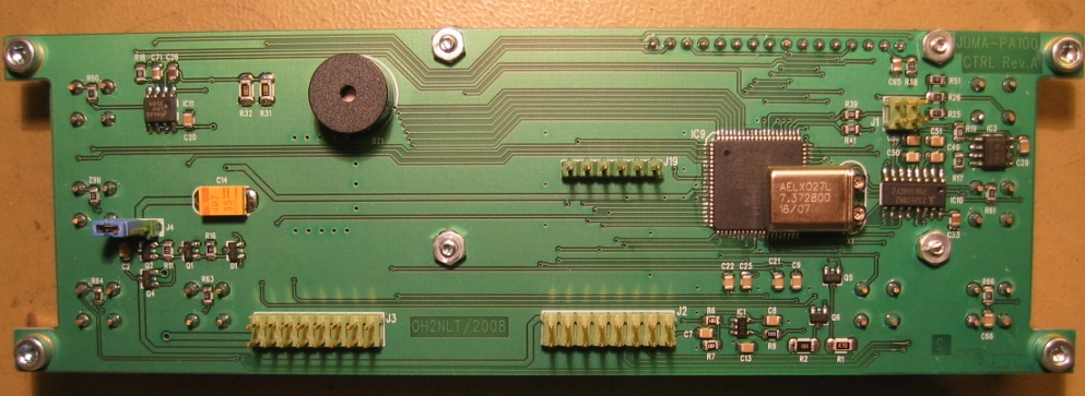
Digital Control Board top view |
|
General
JUMA PA100 Digital Control module provides necessary control signals for the JUMA PA100 main board and for the power amplifier module. Digital Control module measures and displays various analog signals like power, swr and amplifier temperature. Users can select the measured parameters for the display. Display is 2x16 characters size. Output power is shown with a graphical “bar graph” display. User controls are eight push buttons. Please refer to the users manual for push button functions. Digital Control Module monitors SWR, amplifier temperature and drain current measurements. Firmware generates alarms and shuts down the power amplifier if limits are exceeded.
Operating modes
The Digital Control Module can be used to select the amplifier operating frequency manually. Three automatic frequency tracking modes are also supported. Digital control module can communicate with the JUMA-TRX2 through RS232 interface. Yaesu 817 voltage coded band data input is also supported. Digital Control Board circuitry and firmware supports also input frequency sensing technique. F-sense band selection allows JUMA-PA100 automatic band tracking with any SSB / CW transceiver.
Powersupply
Linear regulator is used to generate +5V main operating voltage for the Digital Control board. +5V is also used for microcontroller A/D converter reference voltage. Accuracy of the measurements depends upon +5V. There is a calibration procedure for most A/D measurements in the microcontroller firmware. Push button SW7, Diode D1 and FET transistors Q1 & Q2 forms the firmware controlled power switch. Transistor Q4 switches power f or the main board.
Microcontroller
The dsPIC30F6014A microcontroller is a performance overkill for this application. 30F6014A is however a good choice for this application because of several reasons. Controlling JUMA-PA100 amplifier requires plenty of microcontroller I/O recources. 80-pin 30F6014A microcontroller provides all that we need. The microcontroller is the same that is used in the JUMA-TRX2. This makes logistics and firmware support easier.
Fan control
Power amplifier cooling
fan speed is firmware controlled. Firmware can set three different fan speeds.
Fan motor current is set with R1,R2,Q5 and Q6.
SPI bus
SPI bus is reserved for possible extensions.
F-Sence circuit
F-sense board conditions and limits input RF signal for the frequency measurement. Future signal clipping is done with Schmittrigger inverter IC1. After IC1 the RF signal is counted with microcontroller Timer1 system. Firmware algorithm is used to find out SSB signal frequency.
Digital I/O
Two digital outputs 2DB and 4DB are used to control RF input attenuator. Six digital outputs 1M8…21-28M are used to control filter select relays. OC digital input is the over current indication from the main board. OC-CLR is digital output for clerring the over current protection circuit. KEY is digital input requesting amplifier on. TX+ is digital output controlling the power amplifier on/off state. PWR-SW is digital input indicating power switch button state. PWR-ON is digital output controlling the powersupply on/off switch transistors. FAN1 and FAN2 are digital output signals for the fan control.
RS232 interface
Microcontroller UART1 is connected to RS232 transceiver circuit IC10. RS232 signals are connected via main board to the F-sense board and back plate jack. RS232 interface can be used to connect JUMA-TRX2 and JUMA-PA100 together for band tracking. RS232 inteface can also be used for various JUMA-PA100 tests. Microcontroller UART2 is reserved for future use. UART2 signals are available at connector J1.
Analog measurements
Microcontroller A/D converter is used to measure six different analog signals. Signals are:
ID Power amplifier transistor collector current
BATT JUMA-PA100 operating voltage
BAND Yaesu 817 band select voltage
REW-PWR SWR bridge reflected voltage
FWD-PWR SWR bridge forward voltage
TEMP Amplifier temperature
LCD
A 2x16 character LCD display is used to display the amplifier state and measurements. Firmware loads some custom characters to the display. A bar graph merer is formed and displayed with these custom characters. LCD back light and contrast are user adjustable. Microcontroller PWM unit is used to form two DAC outputs. First DAC R41,C71IC11-A, Q3 and associated components generate adjustable LCD back light current. Second DAC R39, C70 and IC3A provide contrast voltage for the LCD display.
Push buttons
Front panel buttons are momentary switches which firmware reads via microcontroller I/O pins. When button is pressed I/O logic state is “0”. In normal state push button I/O signals are “1” logic state. Switch debounce is done in the firmware.
Feedback tones
User interface feed
back tones are played with a miniature speaker BZ1. Microcontroller timer
and PWM system is used for the sound generation.