All the measurements during the adjustment is done by using the front panel reading
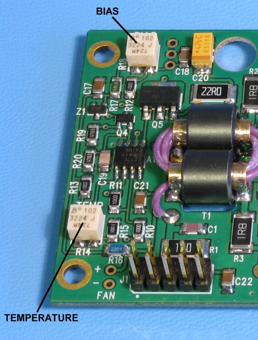
The trimmer R18 adjusts the bias current and the trimmer R14 adjusts the temperature offset
 Click to enlarge
There are two adjustable trimmer resistors (R18 and R14) on the amplifier boardImportant notes before the adjustments, to avoid excessive collector current
All the measurements during the adjustment is done by using the front panel reading
The trimmer R18 adjusts the bias current and the trimmer R14 adjusts the temperature offset
Click to enlarge
- Install all PA100 modules to the enclosure and connect them with the flat cablesBias adjustment trimmers (R18)
- Keep the supply power OFF
- Connect a 50 ohm dummy load to the output
- Initially turn the trimmer R18 fully counter-clockwise for minimum bias
- Double-check the minimum bias by measuring the resistance from trimmer slide R18 to the C18. The reading should be below 10 ohms.
1. Make a 3.5 mm test jack plug with tip connected to the GND sleeveTemperature output adjustment trimmer (R14)
2. Switch ON the power (Current limited power supply recommended)
3. Select current display from the front panel
4. Insert the test jack plug to the T/R input connector in the rear panel
5. Select OPER from the front panel (T/R relay action should be audible)
6. Turn the trimmer R18 clockwise until the current reading indicates 0.50 A ± 0.1 A
7. Select STBY from front panel and disconnect the test jack plug
1. Wait until the amplifier module has cooled to the ambient temperature
2. Select the temperature display from the front panel
3. Turn the trimmer R14 until the temperature reading indicates ambient temperature (typical 25ºC)