 1. Solder first all
the SMD components.
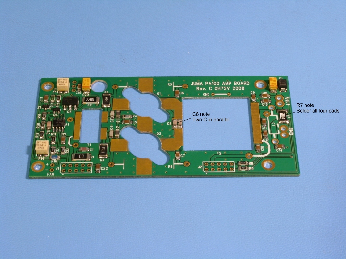
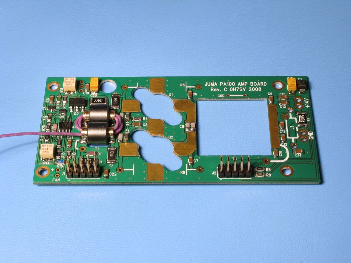
1. Solder first all
the SMD components. Note C8 and R7.
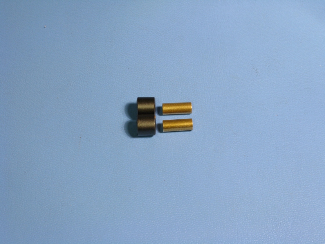 2. Transformer T1
ferrites and the brass tubes. Smooth the inside edges of the tubes if needed.
2. Transformer T1
ferrites and the brass tubes. Smooth the inside edges of the tubes if needed.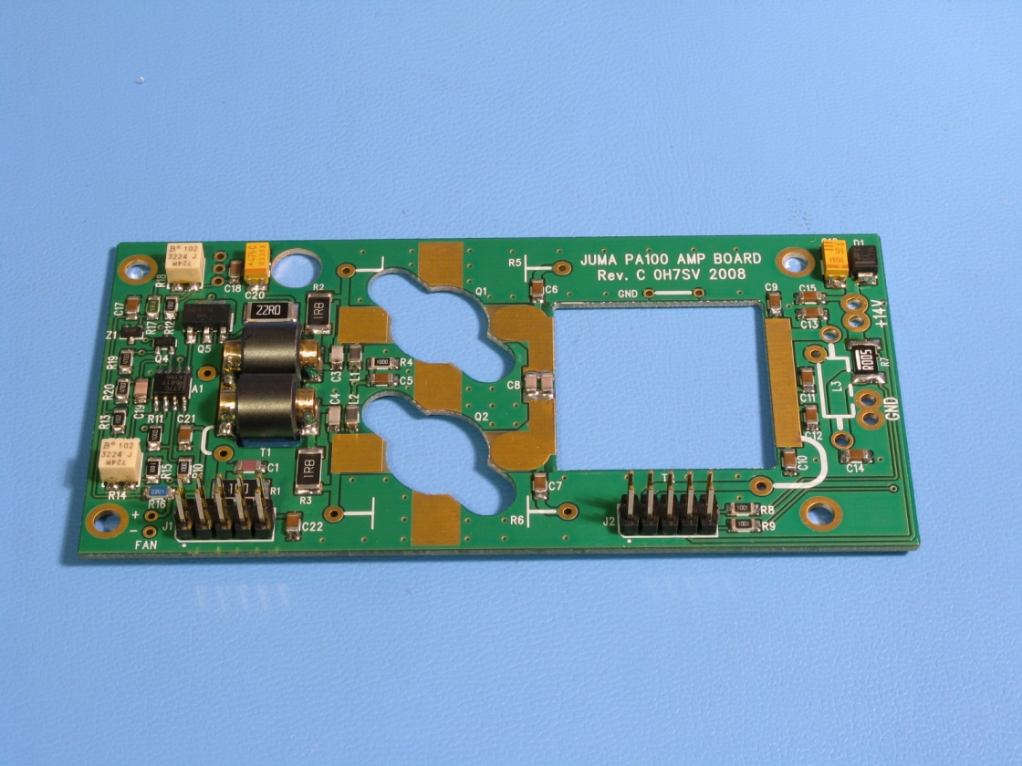 3. Solder T1 tubes
with the ferrite beads. Solder the pin header connectors.
3. Solder T1 tubes
with the ferrite beads. Solder the pin header connectors.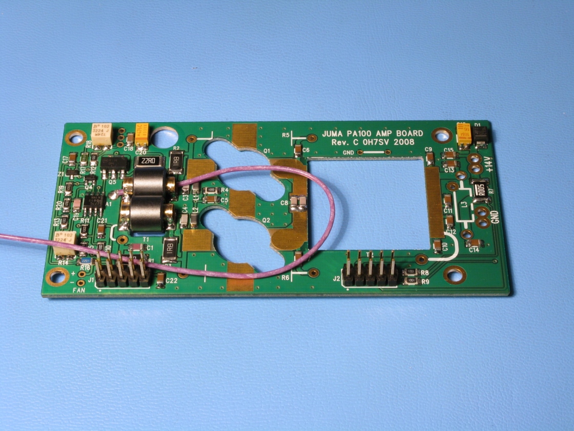 4. Peel one end of
the thinner PTFE wire
4. Peel one end of
the thinner PTFE wire and solder the beginning of the wire.
 5. Wind the turns
by pushing and gently pulling the wire four times thru both tubes.
5. Wind the turns
by pushing and gently pulling the wire four times thru both tubes.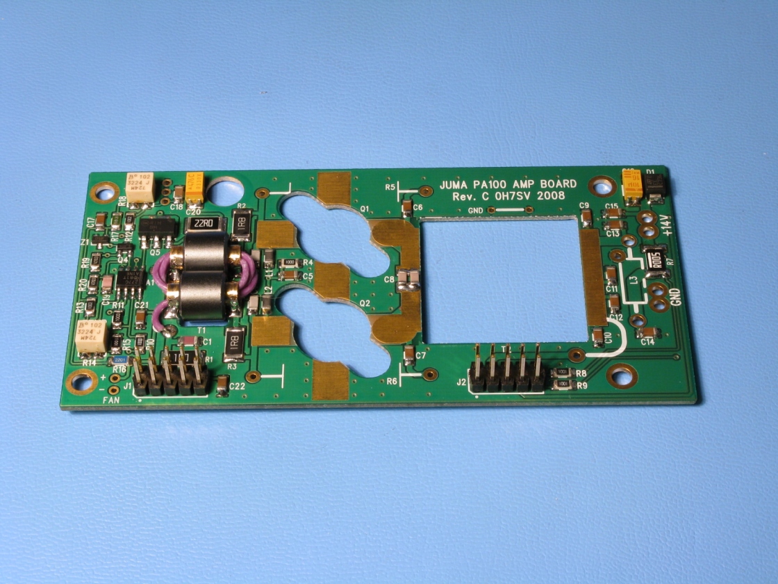 6. Cut and peel the
other end of the wire and solder the end point of the T1 winding
6. Cut and peel the
other end of the wire and solder the end point of the T1 winding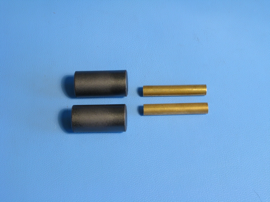 7. Transformer T2
ferrites and the brass tubes. Smooth the inside edges of the tubes if needed.
7. Transformer T2
ferrites and the brass tubes. Smooth the inside edges of the tubes if needed.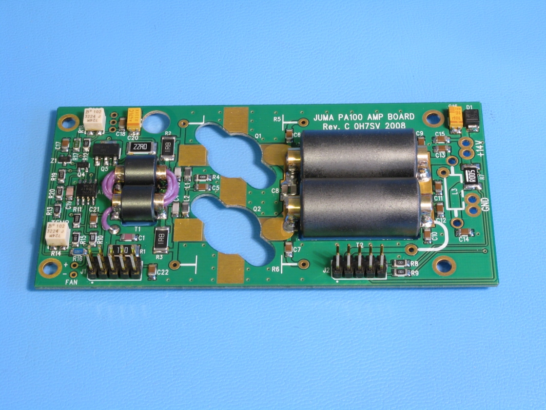 8. Solder the transformer
T2 brass tubes with ferrites.
8. Solder the transformer
T2 brass tubes with ferrites.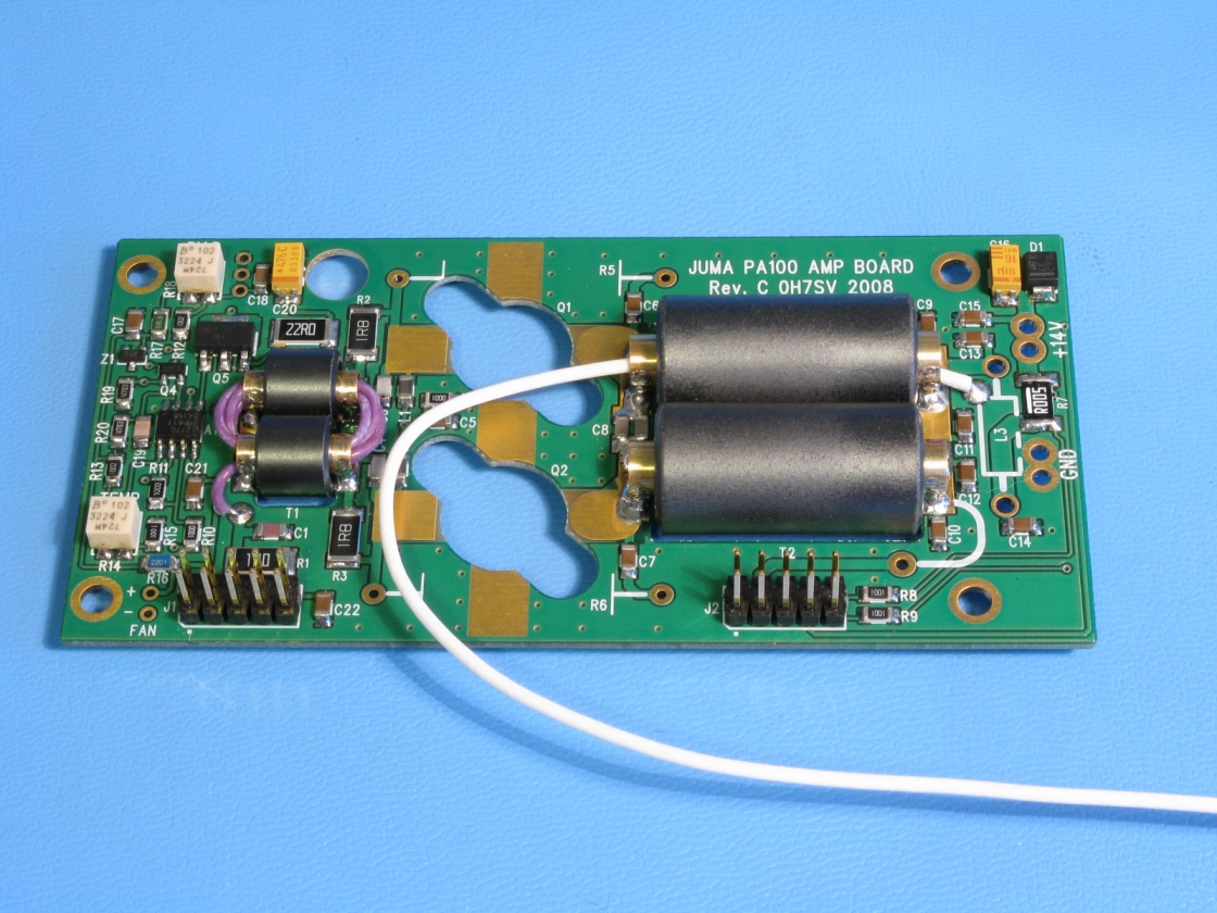 9. Peel one end of
the thicker PTFE wire
9. Peel one end of
the thicker PTFE wire and solder the beginning of the wire.
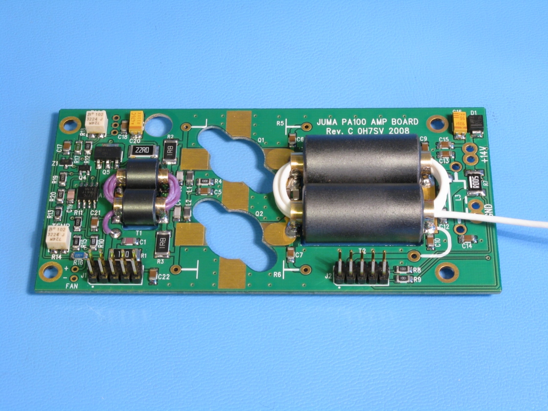 10. Wind the turns
by pushing and gently pulling the wire four times thru both tubes.
10. Wind the turns
by pushing and gently pulling the wire four times thru both tubes.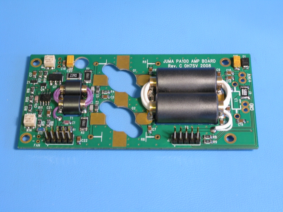 11. Cut and peel
the other end of the wire and solder the end point of the T2 winding
11. Cut and peel
the other end of the wire and solder the end point of the T2 winding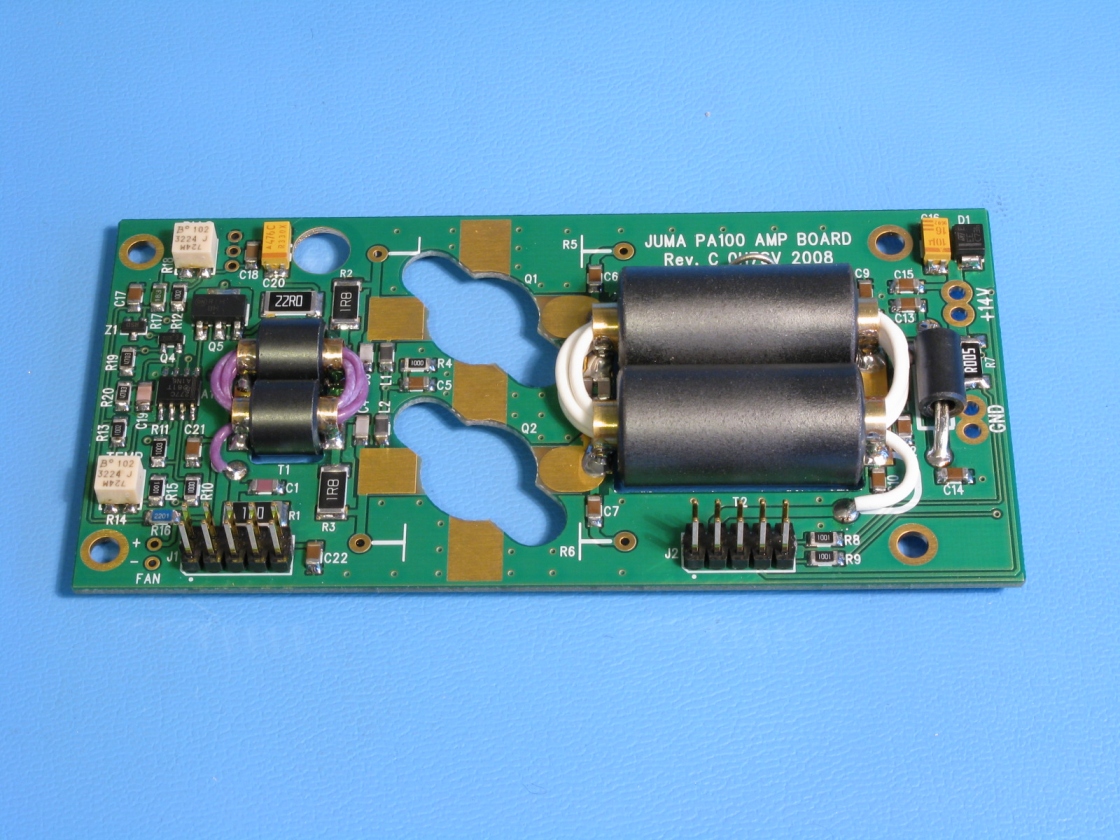 12. Solder L3 with
two copper wires thru the ferrite bead. Solder also GND jumper near T2.
12. Solder L3 with
two copper wires thru the ferrite bead. Solder also GND jumper near T2. 13. Install the fan
with the finger shield to the heatsink. (Finger shield missing in this picture)
13. Install the fan
with the finger shield to the heatsink. (Finger shield missing in this picture)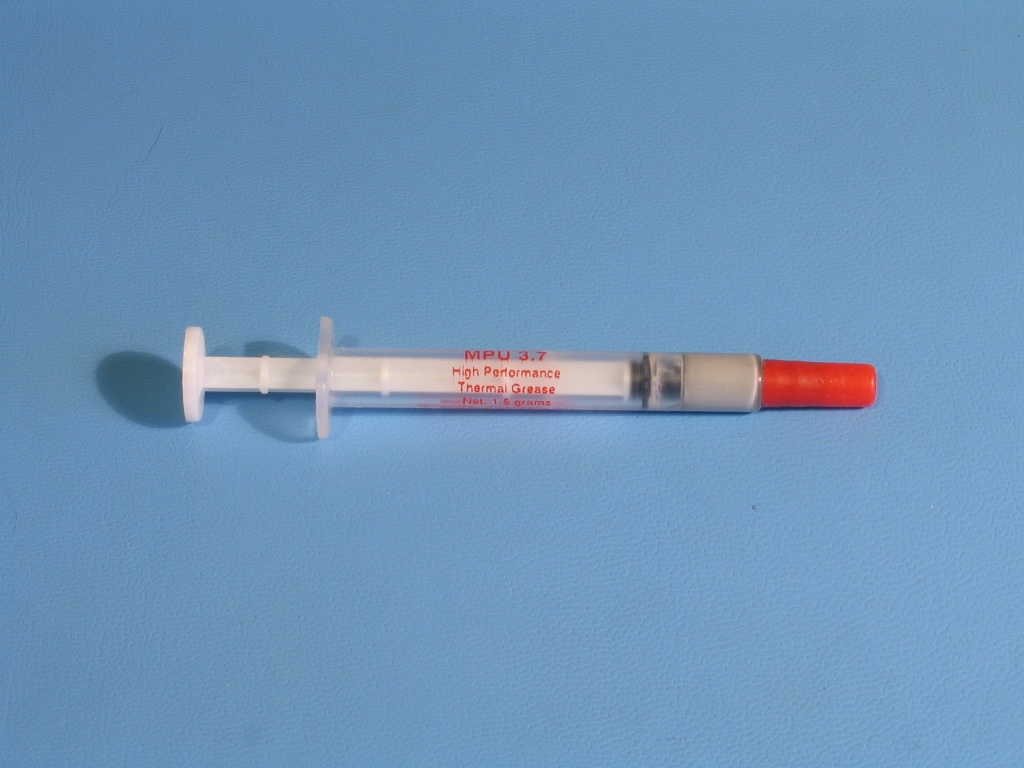 14. Thermal grease
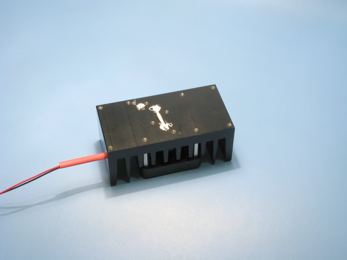 15. Apply thermal
grease to the heatsink as shown in the picture
15. Apply thermal
grease to the heatsink as shown in the picture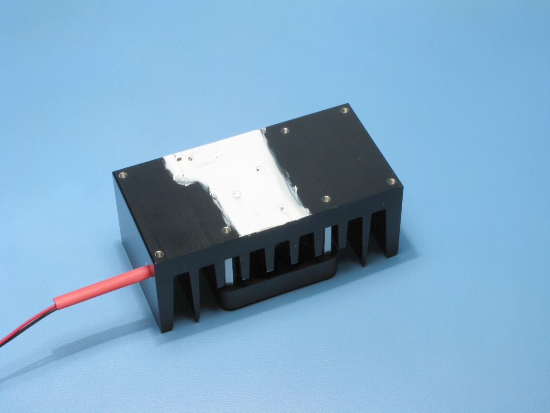 16. Smoothen the
grease over the shown area.
16. Smoothen the
grease over the shown area. 17. Prepare the Q3
by folding the legs of the transistor as shown
17. Prepare the Q3
by folding the legs of the transistor as shown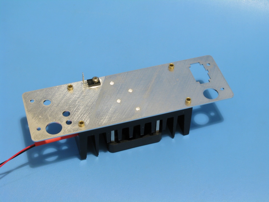 18. Place the rear
plate. Apply thermal grease and install Q3. Place the PCB spacer tubes.
18. Place the rear
plate. Apply thermal grease and install Q3. Place the PCB spacer tubes.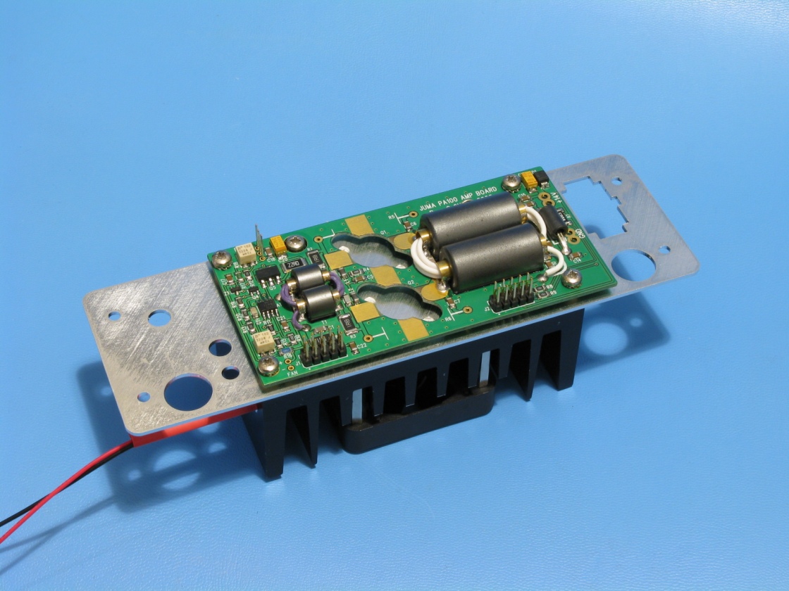 19. Fix the PCB.
Tighten the screws loosely and align the board, the rear plate and the heatsink.
19. Fix the PCB.
Tighten the screws loosely and align the board, the rear plate and the heatsink.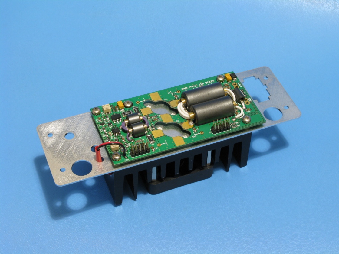 20. Put the fan wires
thru the rear plate and solder the fan wires.
20. Put the fan wires
thru the rear plate and solder the fan wires.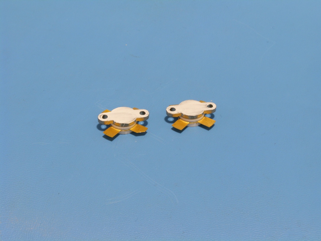 21. Apply thermal
grease to the final transistors.
21. Apply thermal
grease to the final transistors.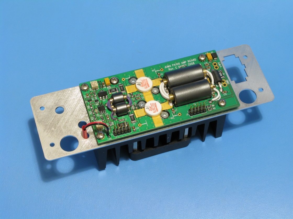 22. Mount the final
transistors Q1 and Q2. Tighten the screws loosely and align all.
22. Mount the final
transistors Q1 and Q2. Tighten the screws loosely and align all.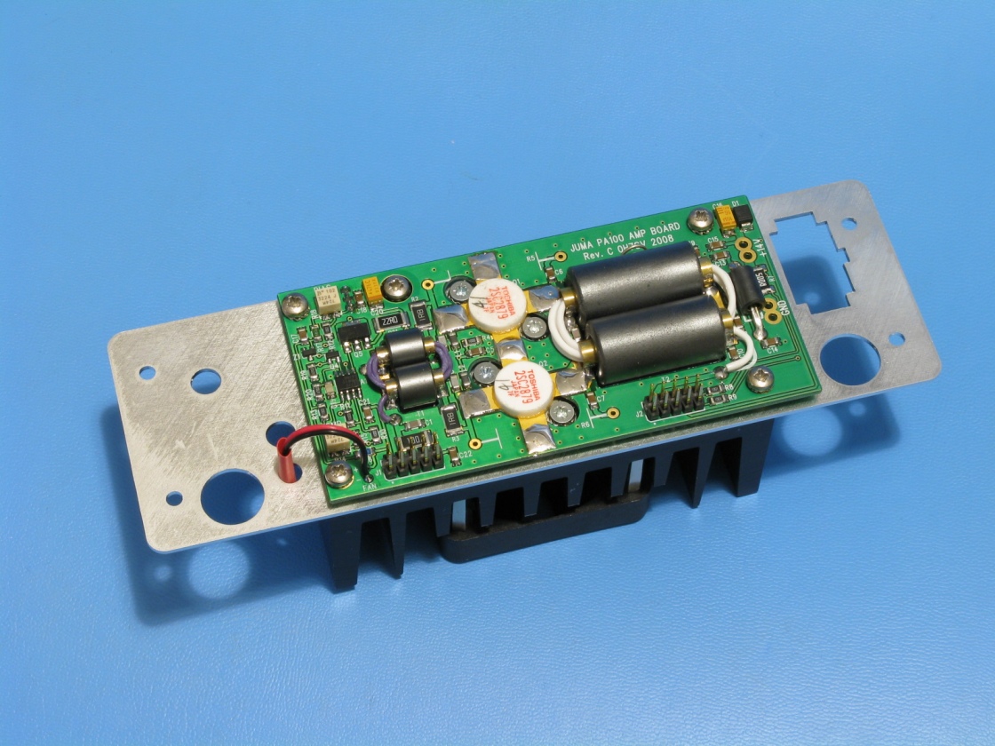 23. Tighten alternately
all the screws and solder Q1 and Q2 legs. Use large soldering tip
23. Tighten alternately
all the screws and solder Q1 and Q2 legs. Use large soldering tip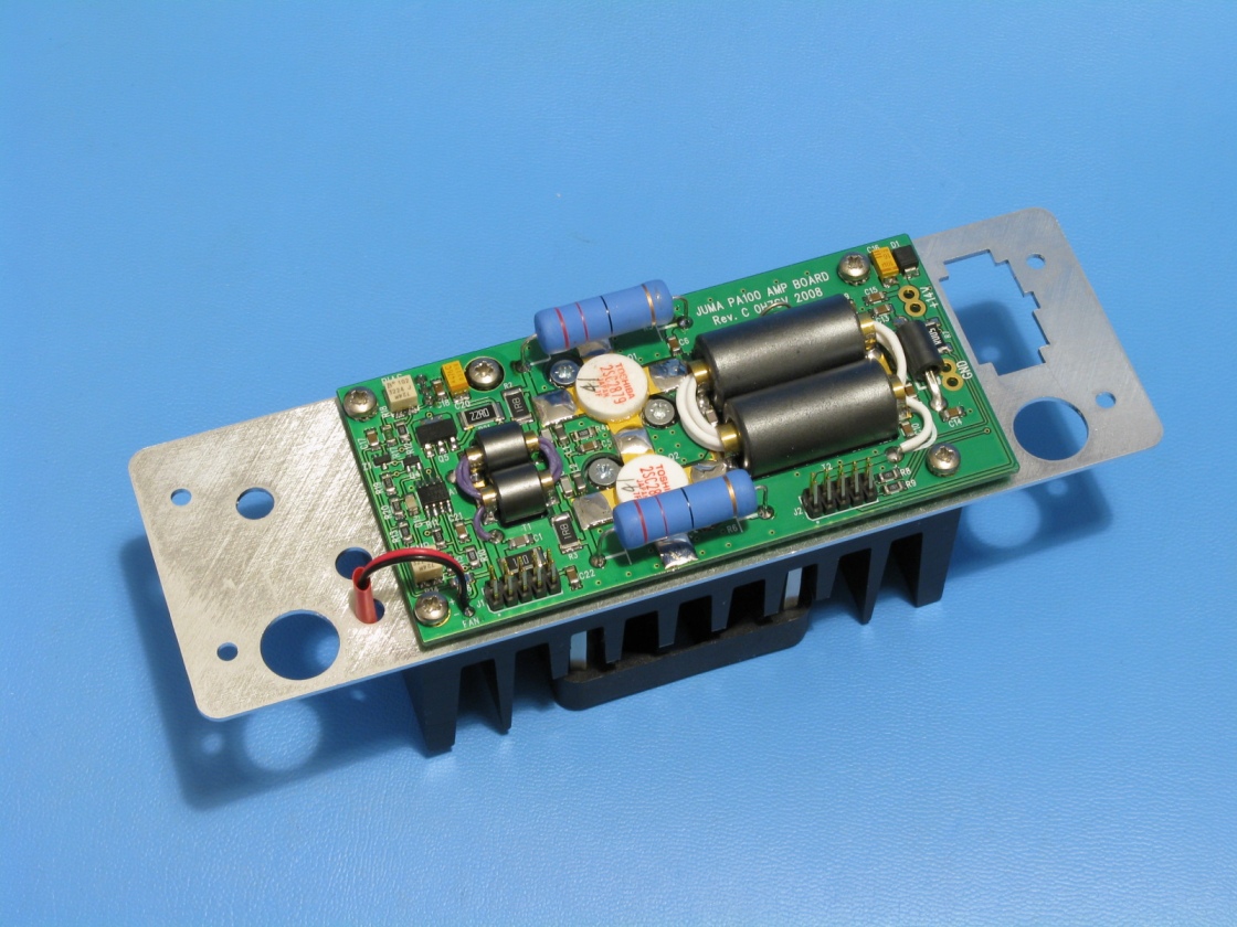 24. Check all the
screws and solder Q3 legs. Solder the power resitors R5 and R6.
24. Check all the
screws and solder Q3 legs. Solder the power resitors R5 and R6.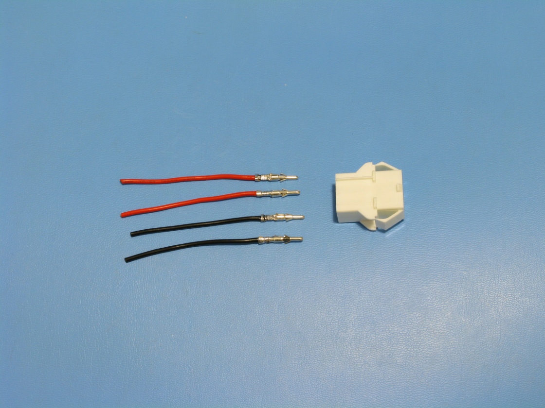 25. Cut and peel
the red and black wires. Crimp and solder to the connector pins.
25. Cut and peel
the red and black wires. Crimp and solder to the connector pins.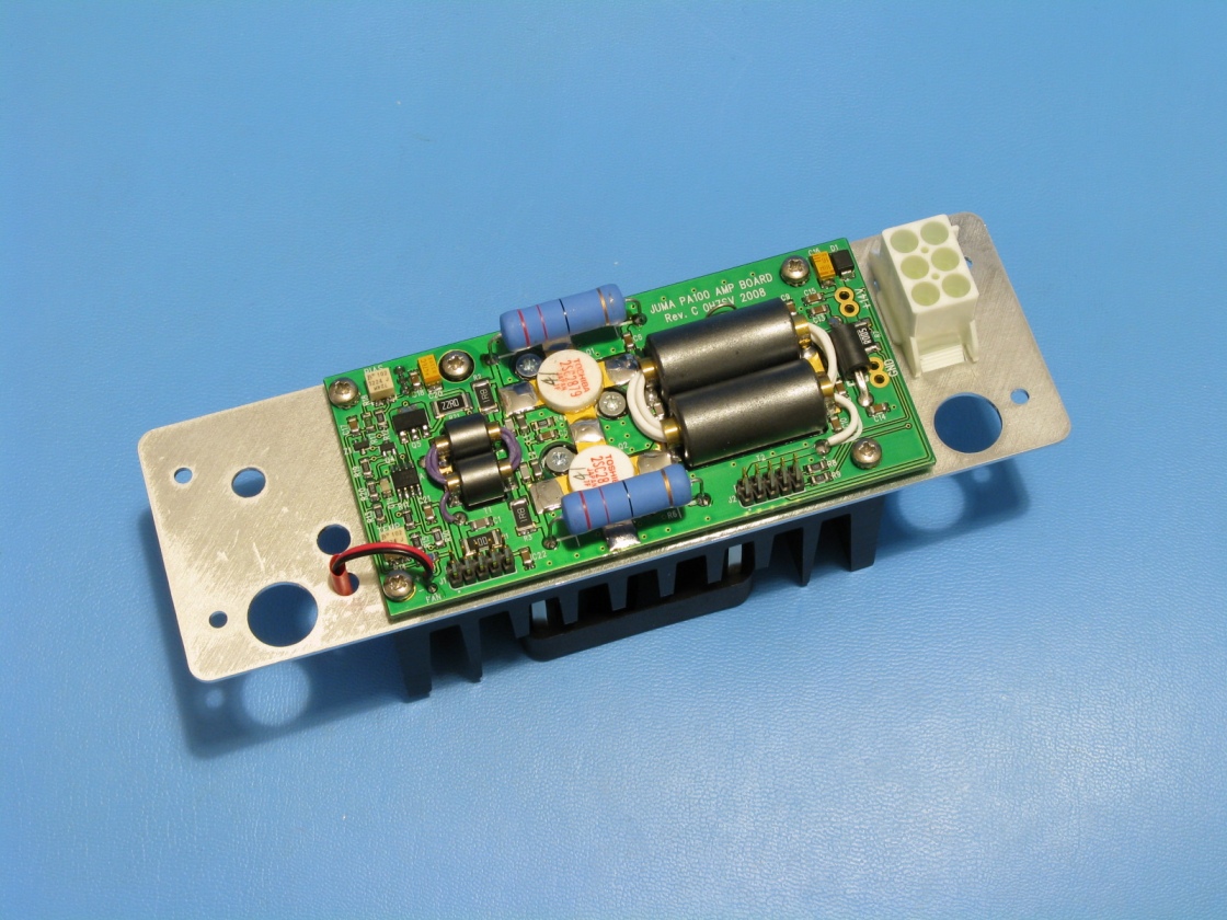 26. Snap in the power
supply connector to the rear panel.
26. Snap in the power
supply connector to the rear panel.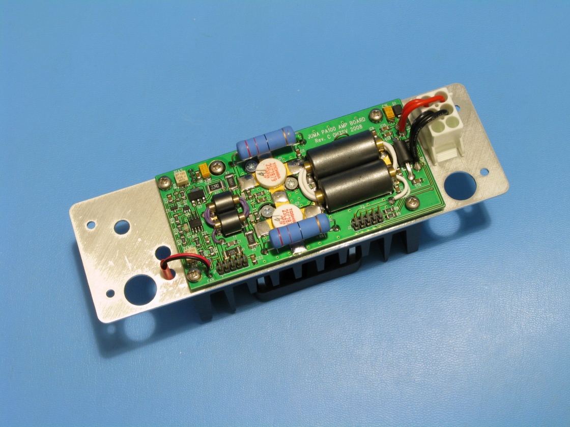 27. Snap the connector
pins to the connector. Cut, peel and solder the wires to the PCB.
27. Snap the connector
pins to the connector. Cut, peel and solder the wires to the PCB.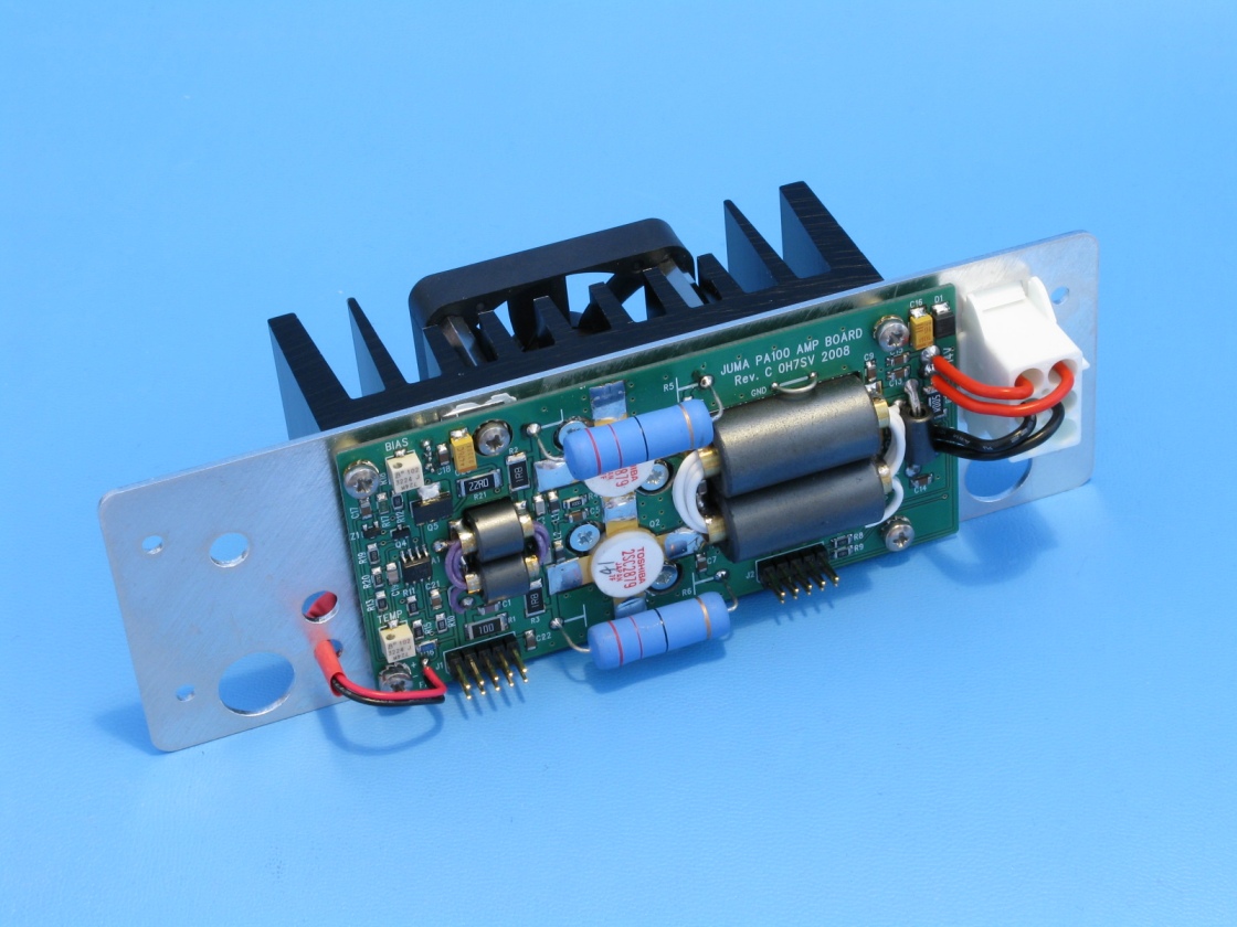 28. Completed amplifier
module
28. Completed amplifier
module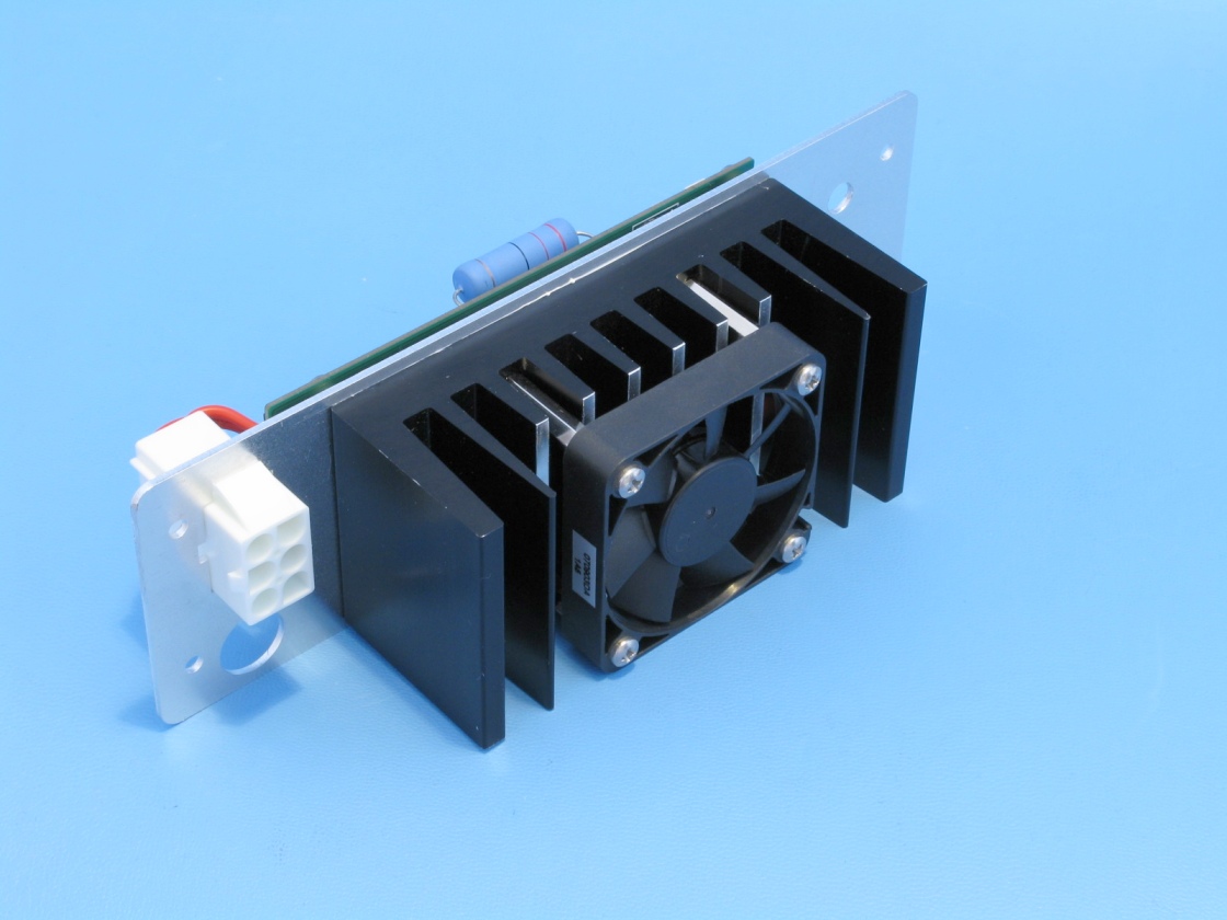 29. Completed amplifier
module
29. Completed amplifier
module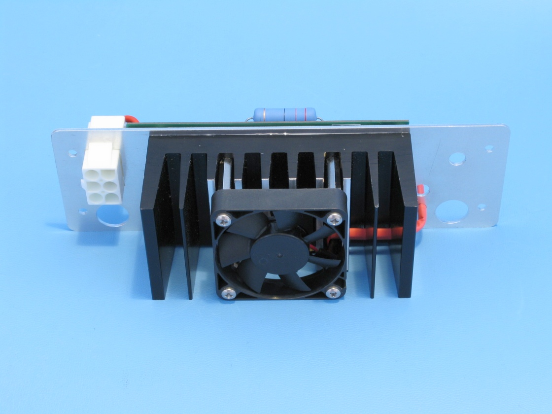 30. View of the fan
cable
30. View of the fan
cable