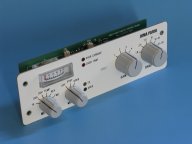
General
The Analog Control module
controls all the function of the analog JUMA PA100 model. It is using rotary
switches, moving coil meter and LEDs for user interface.
Band selection
The right most rotary type
BAND switch (SW4) has 6 positions for different bands. The switch is connecting
+5V to the corresponding band signal which goes to the main board to activate
the desired band low-pass filters by means of the relays. Bands 14/18 MHz
and 21/24/28 MHz are using the same filters, thus 6 positions of the band
switch handles all 9 HF bands.
Gain selection
The rotary type GAIN switch
(SW3) is controlling the input attenuator of the PA100 amplifier in binary
manner. There are 4 gain positions which will adjust the PA gain in 2 dB
steps.
Mode selection
The rotary type MODE switch
(SW2) has 3 positions OFF - STBY and OPER. The switch is supplying the +14V
to the control board circuit and it handles the Standby/Operate states via
the TX signal. The LED4 is lit when the OPER is selected and the LED3 will
be lit during transmission. The LED5 is installed inside the moving coil
meter and it is lit when the power is switched on, i.e MODE switch is in
the STBY or OPER position. This LED will illuminate the meter scale.
Meter selection
The left most rotary type
METER switch selects what is indicated in the moving coil meter, Current,
Voltage, Temperature, relative Reverse power or relative Forward power. Each
measured parameters are scaled with resistors R15-R21 to same voltage level.
After the rotary switch the signal is fed to the peak detector (A2-A) and
buffered for the moving coil meter. The peak detector has a fast rise time
(1 ms) and a slow fall time (1s) to achieve good meter readability also during
SSB transmission. The nominal voltage range to the moving coil meter is 0-2
VDC which can measured in the test point TP1. The trimmer R29 is used to
calibrate the moving coil reading. See adjustment instructions in the separate
Adjustment instruction.
Protection circuits
The analog control board
is monitoring the PA heatsink temperature. The comparator A1-B takes care
of the over temperature protection. PA100 will be forced to the standby
state and the corresponding LED2 will be lit if the temperature protection
limit 80°C is exceeded.
The analog control board is also monitoring the over current signal coming from the main board. This signal is handled by the MOSFET TR3 which will force PA100 to standby state in case of over current (24 A) and the LED1 will be lit. The over current protection is latching type and it must be reset by user with the MODE switch.
Cooling fan control
The temperature signal 0-2V
(0°C-100°C) is also used to control the cooling fan with the comparator
A1-A. The starting temperature of the fan is adjusted by the trimmer resistor
R2. Middle position of trimmer (default) corresponds 55°C and the adjustment
range is 37°C-75°C.