JUMA PA100
F-sense Board Module description, Last update 2008-11-30 OH7SV
Refer to the schematics page
|
 F-sense
board
F-sense
board
|
F-sense
board installation |
General
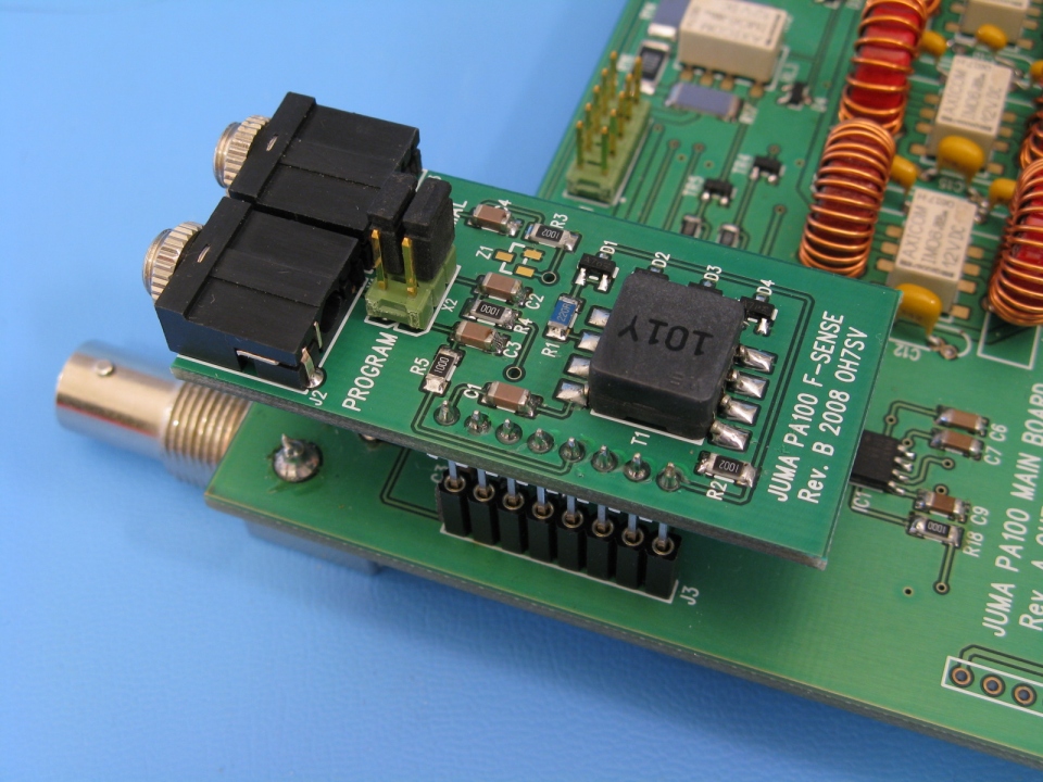
The F-sense
module is used only in digital model PA100-D. The board has three functions.
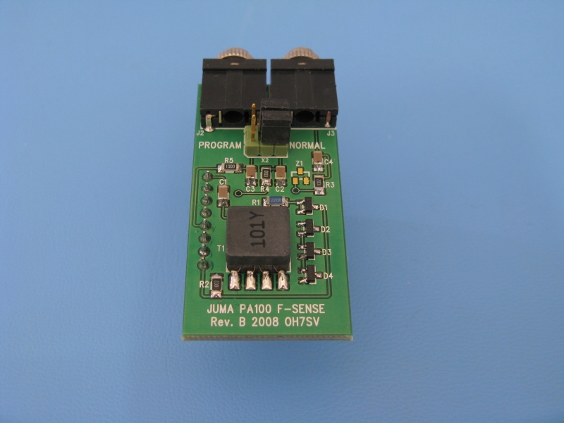
1. Frequency sensing
The board provides clipped RF signal at suitable level for the digital
control module for automatic band detection. The transformer T1 is used to
pick up the exciter RF signal. The diodes D1...D4 with the resistors R1
and R2 are keeping the F-sense RF signal at proper level for the digital
control board.
2. RS232 connection
The jack type socket J2 provides RS232 connection for JUMA TRX2 or PC
connection for firmware programming. There are two jumper blocks which are
used to select between straight and cross connected TXD and RXD
wiring. The jumper selection allows to use commercial jack - jack audio cable
for TRX2 RS232 connection. This jumper position is marked "NORMAL" on the
board. When the RS232 connections is used to update the firmware with a PC,
the "PROGRAM" jumper position should be selected. This way the JUMA TRX2
PC cable can be used. See the PC cable
wiring.
3. Band
DC voltage input
The jack type socket
J3 provides Yaesu
FT-817 (or similar) type DC band selection input. The DC voltage is connected
into the jack tip terminal.
Yaesu FT-817 band data DC voltage levels (nominal values)
BAND VOLTAGE
1.8 MHz 0.33 V
3.5 MHz 0.67 V
7 MHz 1.00 V
10 MHz 1.33 V
14 MHz 1.67 V
18 MHz 2.00 V
21 MHz 2.33 V
24 MHz 2.67 V
28 MHz 3.00 V
Voltage tolerance
for JUMA PA100 is ± 0.10 V.
Band voltage levels below
0.23 V and over 3.10 V are not valid band data for PA100-D.
 F-sense
board
F-sense
board