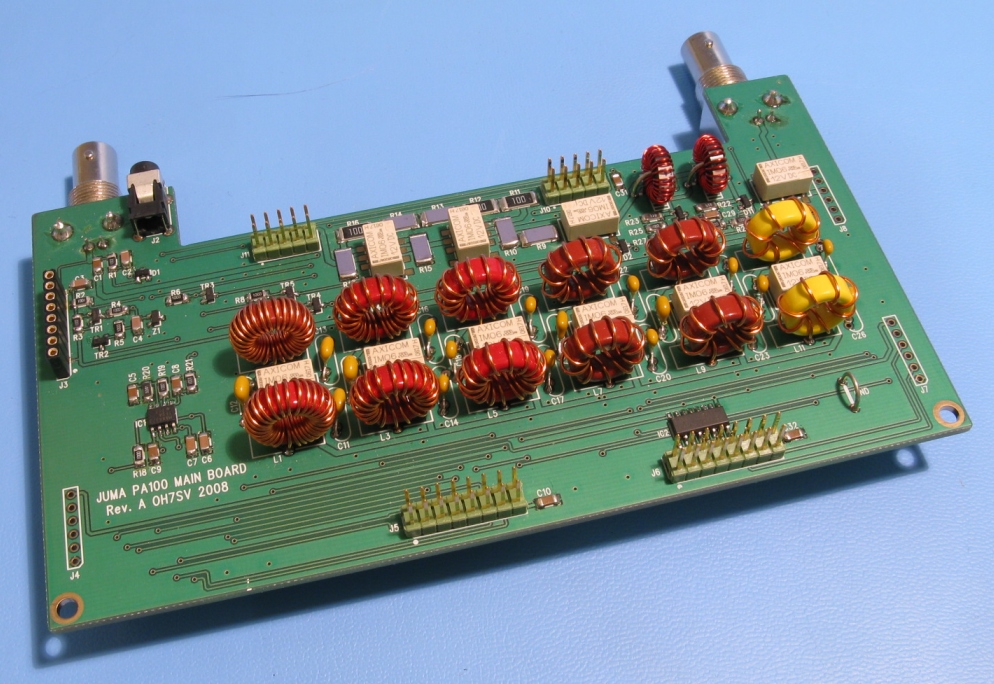
General
The main
board handles T/R switching, RF gain, low-pass filtering, FWD/REV power
sensing and current sensing. The board is wired to the control module and
to the RF amplifier module with flat cables. There is also a pin header
connector (J3) for the F-sense module which is used in PA100-D digital model.
Transmit/Receive
control
There are
two methods for T/R switching (PTT control). In case of JUMA exciters the T/R switching is fed
via the RF coaxial cable as DC current from exciter to the PA100. Thus no
extra PTT cable is needed with JUMA exciters. In case of other exciters a PTT cable is needed
between an exciter
and PA100. It
is a grounding signal (open collector, open drain or relay signal) to the
tip of the KEY IN/OUT jack socket J2. The required sink current is less
than 2 mA. TR1 handles this KEY IN detections. The final T/R switching signal
(KEY => +TX) is routed via the control board which controls the T/R relay
RL1 by means of the MOSFET TR3. The exciter RF is passed by directly to the
ANT connector in STBY state. During TX state the RF is fed to the input of
the PA100 amplifier and the amplifier output is connected to the ANT connector.
Input attenuator
The relays
RL2 and RL3 and the related resistors form a RF input attenuator. This
allows operation with various exciter power levels (3W...10W). There are
four selectable
gain levels in 2 dB steps.
Low-pass filters
There are 6 low-pass filter blocks on the board which will attenuate
the harmonics. The filters are switched with the relays R4...R9 by means
of the relay driver IC2. Each lower band (1.8/3.5/7/10 MHz) is using an
own low-pass filter and the upper bands have one filter block for 14/18
MHz and another
for 21/24/28 MHz. The RF coils are constructed using iron powder toroidal
cores. See winding instructions.
Current sense
IC1 is a high
side current sensing circuit. The circuit is sensing the differential voltage
across the 0.005 ohm shunt resistor R7 in the RF amplifier module. The
circuit provides current dependent voltage of 0.1V/A
for the control board. The current sensing circuit also includes a latching
type over current detector. The over current level (default 24 A) is set with the resistors
R19 and R20. The current signal value and over current state is handled by
the control board.
Forward and reverse
power sensing (SWR bridge)
The toroidal
transformers T1 and T2 are measuring RF voltage and RF current. The transformers
are combined for relative forward and relative reverse outputs. These signals
are rectified with the diodes D11 and D12 and fed to the control module.
There are no adjustments in the main board.