Note. These are 2.5A model pictures but the installation is similar for 5A model.
Click the pictures to enlarge
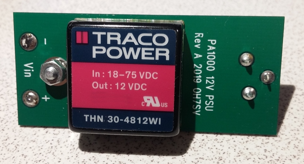
12V PSU option top view
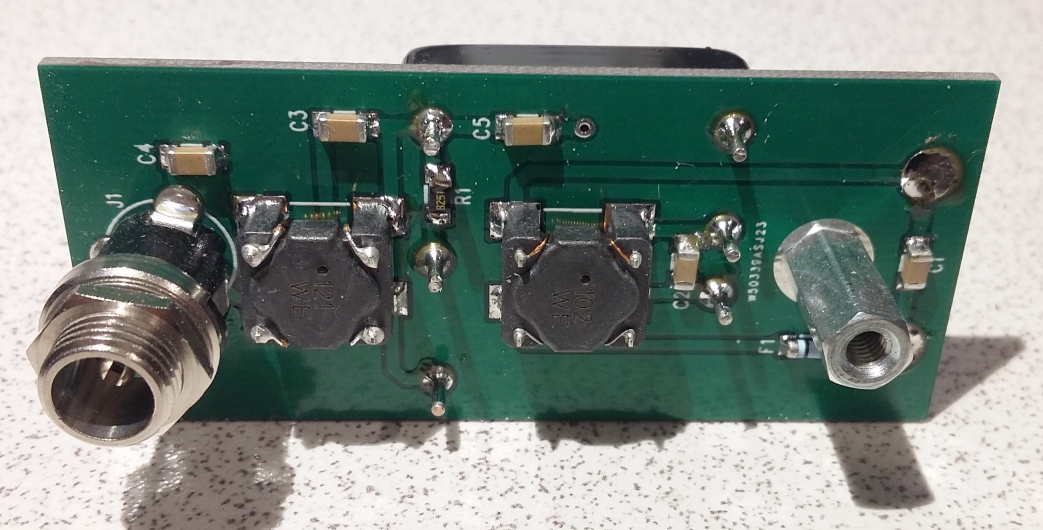
12V PSU option bottom view.
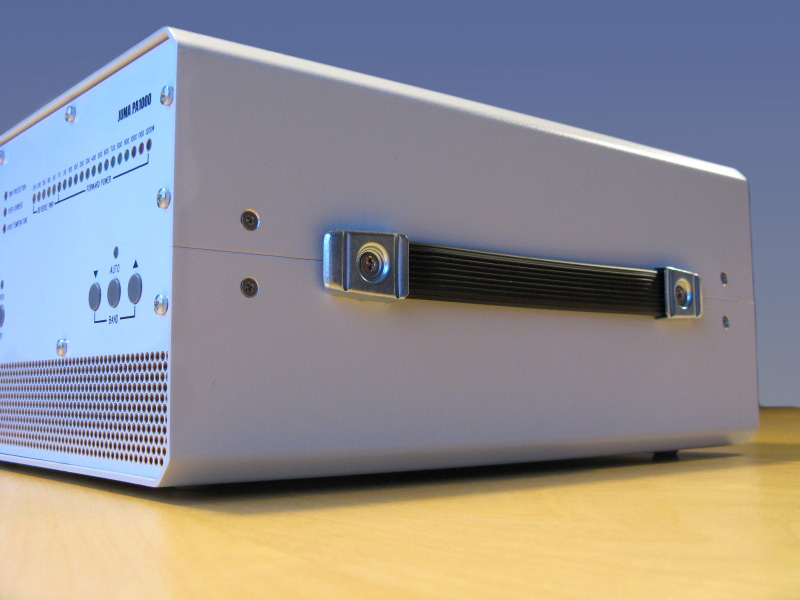
Loosen the two carry handle screws but do not fully remove the screws.
Remove the four bottom cover screws.
Raise the bottom cover from the carry handle side
with care not to damage the power supply wires.
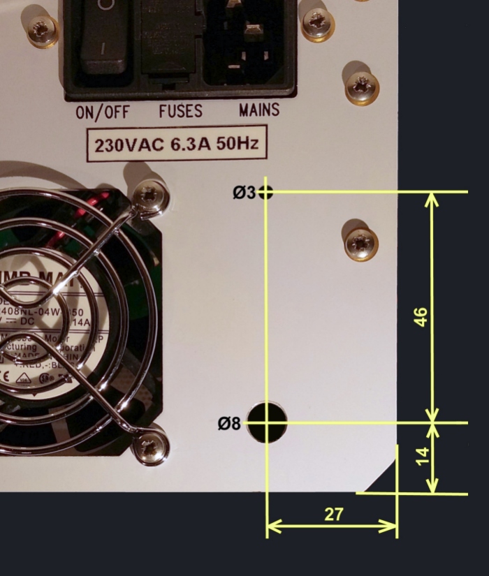
Drill two holes, a 3 mm and a 8 mm hole as shown.
The rear panel is made of PCB.
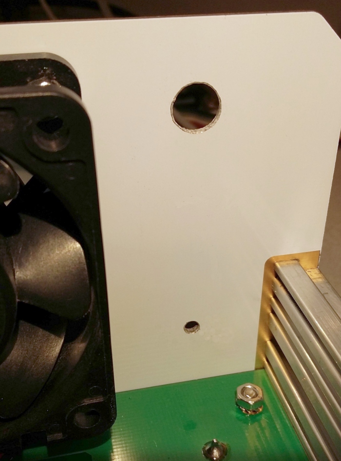
The drilled holes seen inside.
Clean the drilling remains with a vacuum cleaner.
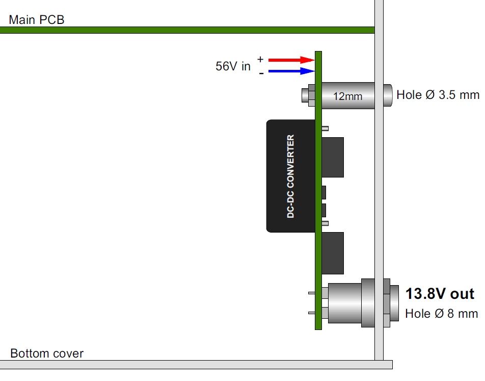
12V option construction.
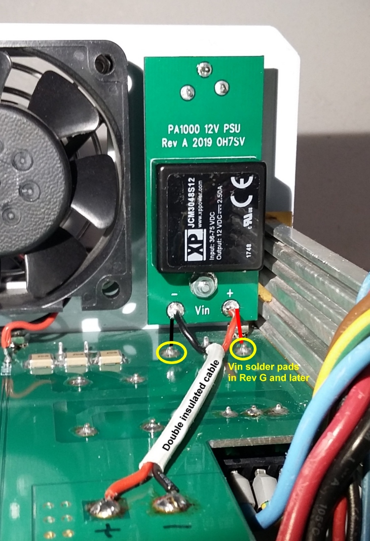
Install the module with the connector nut and with a 3 mm screw.
Use a double insulated cable in older main board revisions or
single wires in Revision G (and later) to the dedicated solder pads.
Reinstall the bottom cover by aligning it to the top cover.
Re-tighten the carry handle screws tightly.
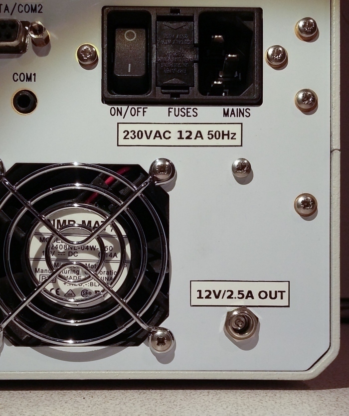
Insert the 12V/2.5A OUT or 12V/5A OUT sticker.
Test the output voltage. Ready to use the 12V out option.
Update 2023-10-28
Back to JUMA PA1000 main page