JUMA PA1000 Performance
Measurements Update
2017-10-19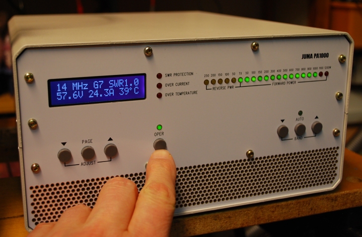
JUMA
PA1000 in Performance Test
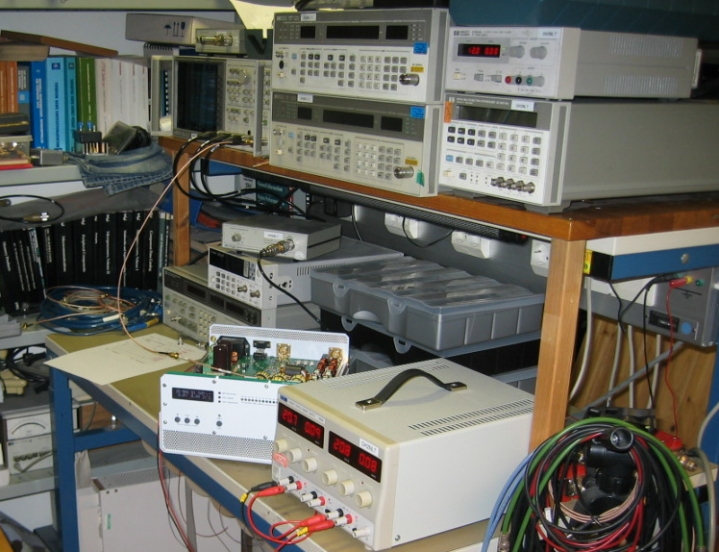
Test setup view 1 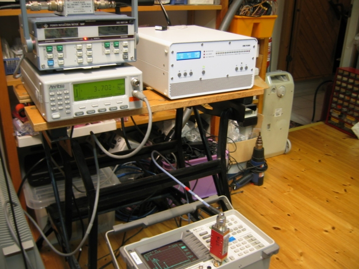
Test setup view 2 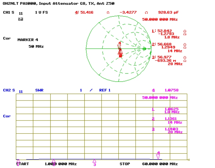
Input
match on
Smith Chart and SWR with gain G8
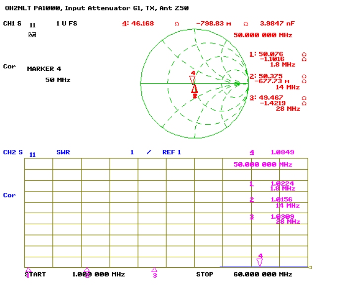
Input
match on
Smith Chart and SWR with gain G1
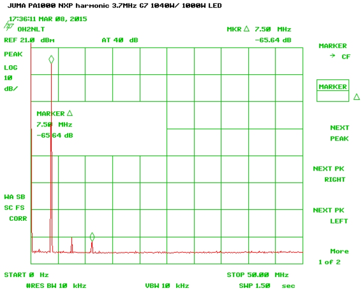
Harmonics on 3.5MHz (2f and 3f at -65.6dBc) 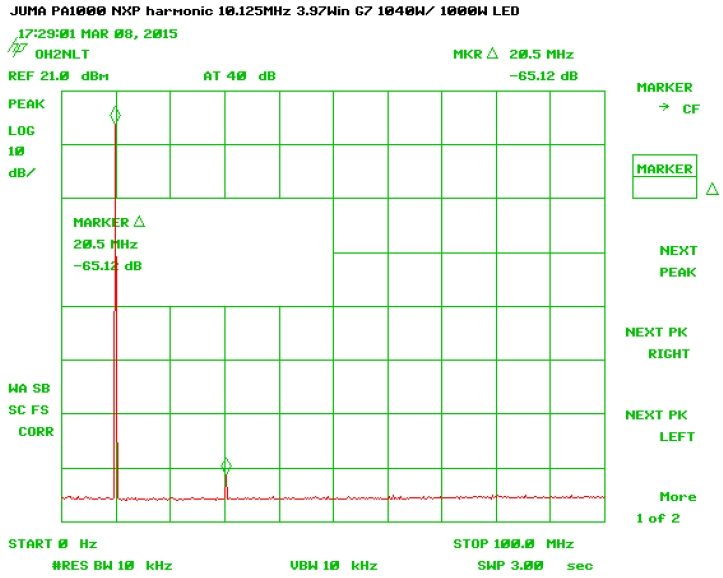
Harmonics on 10MHz (3f at -65.1dBc) 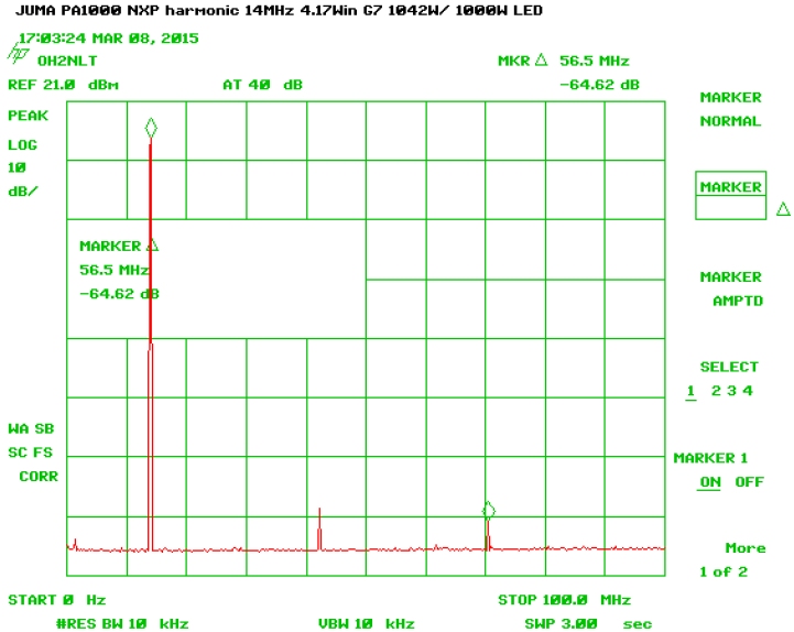
Harmonics on 14MHz (3f at -63dBc and 5f at -64.6dBc) 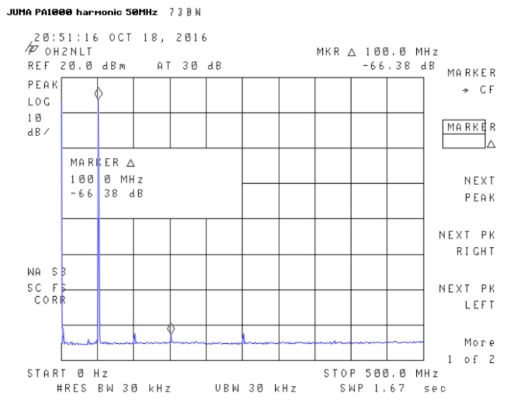
Harmonics on 50MHz (3f at -66.4dBc) Limitation note. If this is against to the local amateur radio regulations user must increase harmonics attenuation at least by 3.6dB with an external filter or refrain to use 50 MHz band. 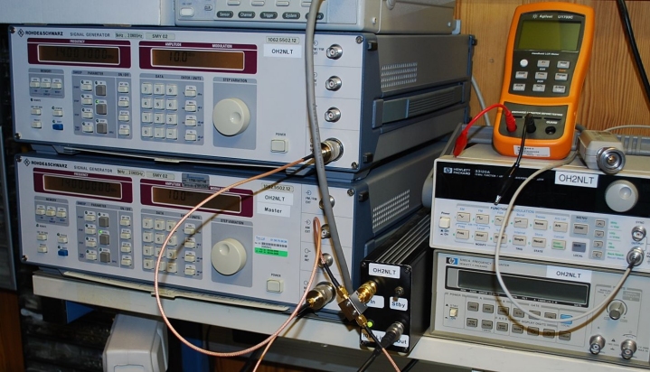
IMD measurement signal is generated with two R&S SMY 02 generators. Two carriers are combined with Mini Circuits ZX10-2-12-S+ splitter and amplified with a 10W wide band amplifier. Amplifier input power is monitored with R&S NAP power meter. Amplifier output is fed to Tenuline 8329-300 30dB power attenuator. After power attenuator signal is split in to two with 6dB Suhner splitter. Additional 10dB Spinner and Suhner attenuators are fitted to both signal paths. One signal path is connected to HP8594E spectrum analyzer. Another signal path is connected to Anritsu ML2437A power meter with MA2421A sensor. Total 46dB of leg attenuator chain is calibrated with generator and power meter. 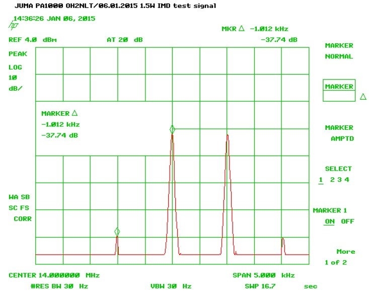
Two tone RF test signal used for measurements (IMD -43.7dBc) 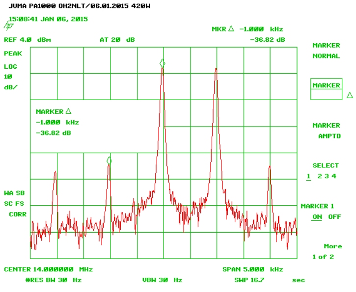
IMD on 14 MHz 420W (-42.8dBc) 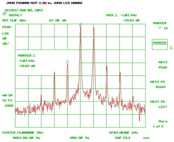
IMD on 14 MHz 1000W (-34.8dBc) 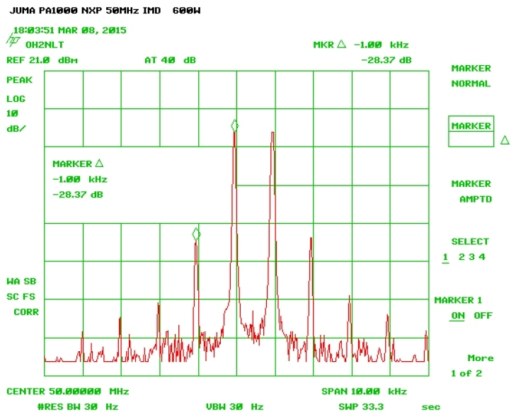
IMD on 50MHz (-34.4dBc) Back to JUMA PA1000 page |