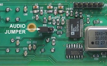
Insert a jumper into the pin header J8, use pins 1-2.
If the Voice Memory is installed, the jumper is not needed.
Audio Jumper J8
Insert a jumper into the pin
header J8, use pins 1-2.
If the Voice Memory is installed,
the jumper is not needed.
Jumper J4
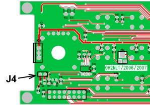
Do not install the jumper J4
for the normal use. It is intended only for test purposes.
If the jumper J4 is installed
you can not switch OFF TRX2 with the PWR button.
LCD-module to the DDS
board connections with pin header
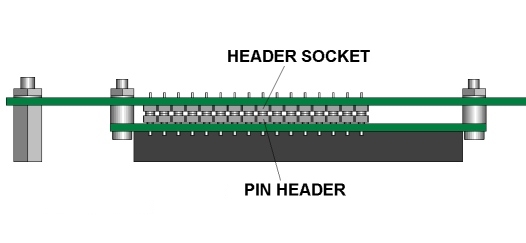
First fix the LCD module mechanically
to the DDS board with the pin headers.
After that solder the the pin
headers to the boards. This is to allow the correct
spacing between the boards
and to align the LCD module with the front panel.
LCD-module to the DDS board
connection with tinned copper wires
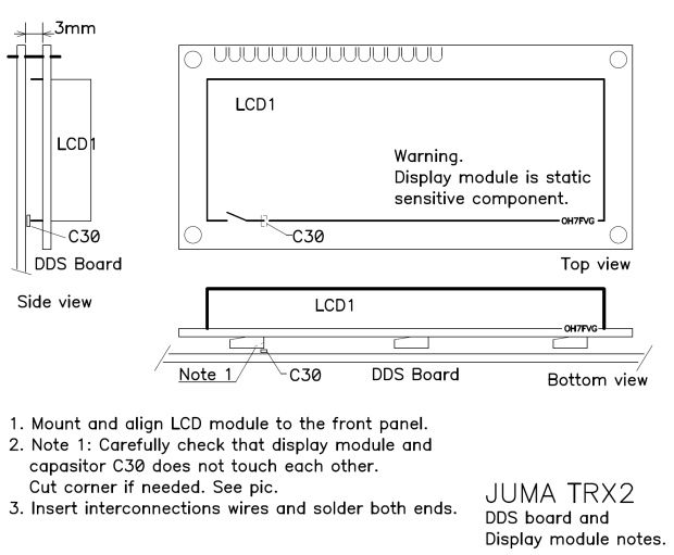
First fix the LCD module mechanically
to the DDS board and align it with the front panel.
After that insert
the interconnection
tinned copper wires and solder them.
MIC socket mounting
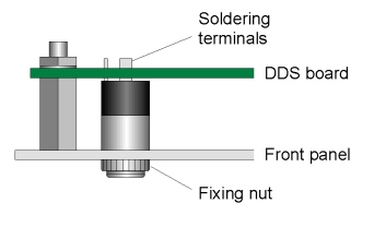
Fix the MIC socket to the front
panel before soldering to the
DDS board
Encoder installation
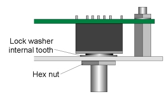
Before tightening the nut check
the lock washer thickness
that the encoder fits perfectly
between the board and the
front panel. When necessary
uninstall the tooth washer
and bang it slightly to a suitable
thickness.