2. Switch ON the power (Current limited power supply recommended)
3. Select CW mode by pushing the MODE button
4. Select Drain Current display (ID -.--A) by pushing the DISPLAY button
5. Press the mic PTT to activate the bias current
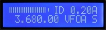
6. Turn the trimmer R6 clockwise until the LCD ID reading indicates 0.03 A ± 0.01 A
7. Turn the trimmer R9 clockwise until the LCD ID reading indicates 0.06 A ± 0.01 A
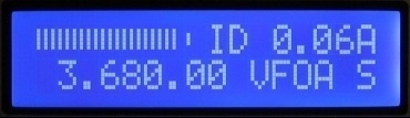
Driver stage bias current
reading 0.06 A after the adjustment