JUMA TRX2 PA Board Adjustments (two band model) Last update 2007-10-14 OH7SV
There are two adjustable trimmer resistors (R4 and R7) on the two band PA board.
All the measurements during the adjustment is done by using the LCD current display
These trimmers define the bias current of the power amplifier MOSFETs.
The bias current is 0.10 A per MOSFET, totally 0.20 A.
Important notes before the adjustments, to avoid excessive MOSFET drain current and the fuse blow
- Keep the supply power OFF
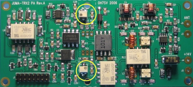
- Initially turn the trimmers R4 and R7 fully counter-clockwise for zero bias
- Double-check the zero bias by measuring the resistance across C5 and C7, the reading should be below 10 ohms
- Inset a current meter (range 1A-2A) in series with power supply cable

Bias adjustments trimmers (R4 and R7)
Note. The trimmers are multiturn models. When turning the trimmers the bias current is not increasing in the beginning. Continue turning until you see an increase of the reading and then fine tune the bias current. Typical trimmer position is approximately in the middle.
1. Switch ON the power (Current limited power supply recommended)
2. Select CW mode by pushing the MODE button
3. Select Drain Current display (ID -.--A) by pushing the DISPLAY button
4. Press the mic PTT to activate the PA bias current
5. Turn the trimmer R4 clockwise until the LCD ID reading indicates 0.10 A ± 0.02 A.
    Cross-check the current reading increase with current meter!

6. Turn the trimmer R7clockwise until the LCD ID reading indicates 0.20 A ± 0.02 A


The bias current reading 0.20 A after the adjustment