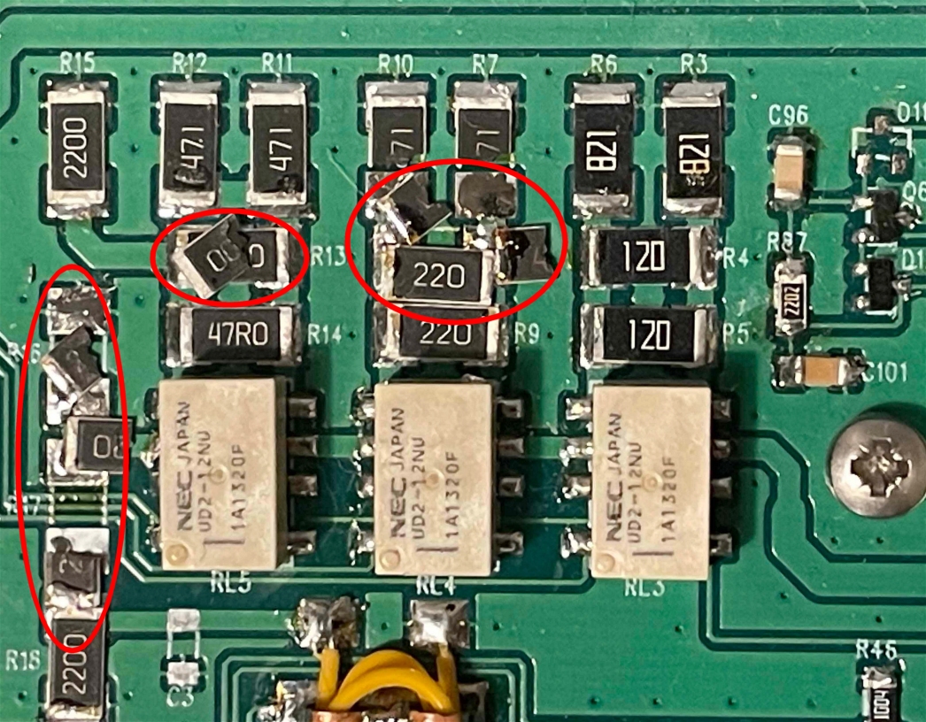
In case you have accidentally over driven JUMA PA1000 you may
have burned some of the adjustable input attenuator resistors. The attenuator
is handling user interface gain (Gx) setting. It is using three binary (1dB,
2dB and 4dB) attenuators which are sequentially taken in to use with the
small SMD relays by firmware control. Typically a burned
resistor can be seen visually. See
here an example of over driven burned resitors.
If your PA1000 has a nominal bias (idle) current (1.5A-2.4A) but it is not transmitting you may have burned the attenuator.
In case of zero bias current follow this instruction.
If your PA1000 has a nominal bias (idle) current (1.5A-2.4A) but it is not transmitting you may have burned the attenuator.
In case of zero bias current follow this instruction.
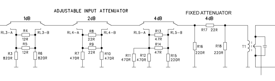
JUMA PA1000 input attenuator schematics
The adjustable input attenuator can stand max 25W RF power but
100W is absolutely too much. The attenuator is using rather big 2512 size
SMD 3W resitors. There is also a fixed 4dB attenuator (R16, R17, R18). You
need to replace only the resistors which have visual marks of failure.
Here is a list of suitable 3W/5% size 2512 SMD resitor part numbers available from DigiKey and Mouser.
12 ohms 2EA 352212RJT
22 ohms 3EA 352222RJT
47 ohms 2EA 352247RJT
220 ohms 3EA 3522220RJT
470 ohms 4EA 3522470RJT
820 ohms 2EA 3522820RJT
22 ohms 3EA 352222RJT
47 ohms 2EA 352247RJT
220 ohms 3EA 3522220RJT
470 ohms 4EA 3522470RJT
820 ohms 2EA 3522820RJT
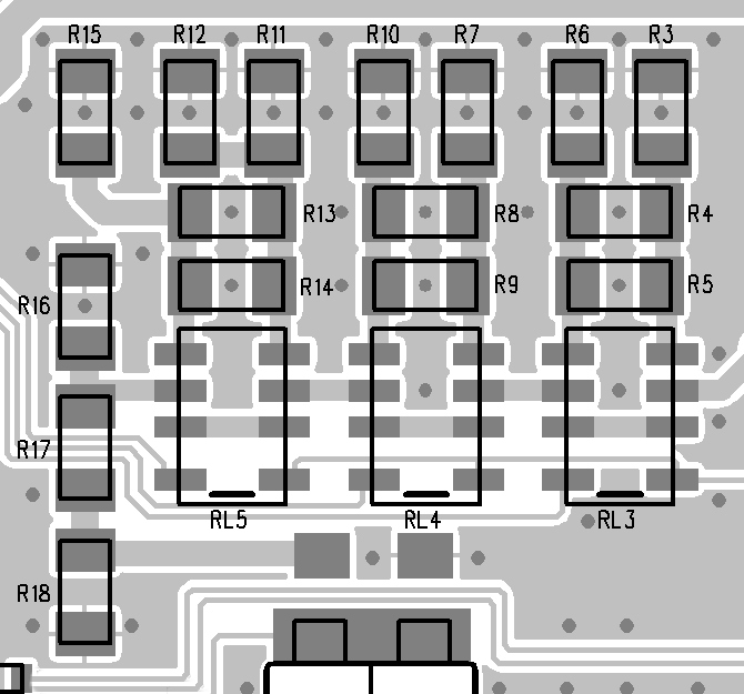
JUMA PA1000 input attenuator layout (location in center
top of main board)
To remove a burned resistor use two soldering irons and heat both
ends of a resitor until it will be freed. After that gently remove residual
solder from the pads with a solder wick. You may wash the area with a brush
and isopropyl alcohol if you like. Add then fresh solder to one pad which
after place a new resistor and reheat the pre-soldered pad. Finally solder
the other end of the resistor.
To open and close the top cover follow this instruction
Update 2023-11-24 OH7SV
Back to JUMA PA1000 additional information
To open and close the top cover follow this instruction
Update 2023-11-24 OH7SV
Back to JUMA PA1000 additional information