JUMA PA1000 was designed before the popular FT8 have been invented.
At that time the design goal was a very light weight
amplifier for SSB and CW. Because of the light weight the cooling does
not allow full power key down operations. Here are few advice
to adapt JUMA PA1000 for FT8.
1. Low PA Voltage reduction to 45V
JUMA PA1000 supports high (56V) and low (50V) PA voltage selection. High PA voltage is recommended for full power SSB to allow headroom for linear operation. The low PA voltage is recommended for all reduced power modes and all carrier type modes like CW. Although the 50V low PA voltage improves the efficiency it may not be enough for FT8. That's why the low PA voltage should be lowered down to abt 45V with the following simple modification.
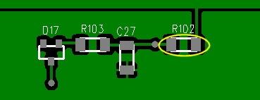
Resistor
R102 about in the middle of the main board defines the low PA voltage
reduction. It is a 1206 size SMD resistor with a typical
value of 390k. By reducing the resistor value to half or more will provide
abt 45V low PA voltage. Instead of replacing the resistor it is easier
to solder a 270k to 330k resistor in parallel. It is not critical, 44V-45V is fine. You will find a suitable
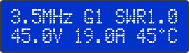
resistor value by following the voltage indication in the LCD.
2. Adjust FAN MAX
RPM

3. Over Temperature Limit change (optional)
JUMA PA1000 is measuring the final LDMOS transistor case temperature instead of the heatsink temperature. Thus it is indicating quite high readings. Nominal over temperature protection limit has been 100ºC. You may consider to raise the limit to 110ºC by replacing the resistor R66 from 15k to 12k.
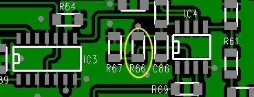
Resistor R66 is located in center top of the main board near IC4
1. Low PA Voltage reduction to 45V
JUMA PA1000 supports high (56V) and low (50V) PA voltage selection. High PA voltage is recommended for full power SSB to allow headroom for linear operation. The low PA voltage is recommended for all reduced power modes and all carrier type modes like CW. Although the 50V low PA voltage improves the efficiency it may not be enough for FT8. That's why the low PA voltage should be lowered down to abt 45V with the following simple modification.
Note that it is normal if he voltage is flickering in standby
state because the power supply is then in discontinuous mode. Operate FT8 with this
new 45V low PA voltage with reduced power of 500W-700W and LCD current indication below 20A.
Adjust FAN MAX RPM to a lower temperature setting. 40ºC setting is available
in the firmware version
v1.35.
See also Silent fan replacement instruction
See also Silent fan replacement instruction
3. Over Temperature Limit change (optional)
JUMA PA1000 is measuring the final LDMOS transistor case temperature instead of the heatsink temperature. Thus it is indicating quite high readings. Nominal over temperature protection limit has been 100ºC. You may consider to raise the limit to 110ºC by replacing the resistor R66 from 15k to 12k.
Resistor R66 is located in center top of the main board near IC4
To open the enclosure top cover follow
this instruction. Please take care of electrical safety!
Update 2023-03-11 OH7SV